Fail:Planar core assembly exploded.png
Mine navigeerimisribale
Mine otsikasti
Selle eelvaate suurus: 800 × 600 pikslit. Teised eraldusvõimed: 320 × 240 pikslit | 640 × 480 pikslit | 1024 × 768 pikslit | 1280 × 960 pikslit.
Algfail (1280 × 960 pikslit, faili suurus: 154 KB, MIME tüüp: image/png)

|
See pilt tuleks konverteerida kasutades vektorgraafikat (SVG-vorming). Vektorkujutisel on mitmeid eeliseid. Konverteerimise kohta vaata täpsemalt siit. Kui sellest pildist on vektorkujutis juba saadaval, siis pane selle malli asemele {{vector version available|uue pildi nimi.svg}}.
|
Lühikirjeldus
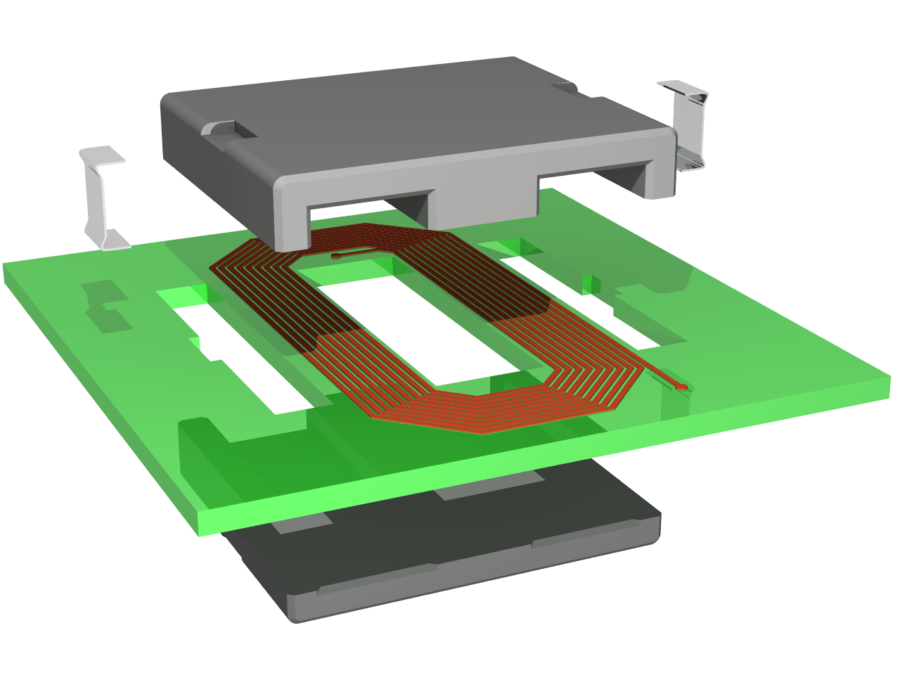
| Kirjeldus | Exploded view of an planar inductor constituted by a spiral track on a printed circuit board and a planar magnetic core |
| Kuupäev | |
| Allikas | Üleslaadija oma töö |
| Autor | Cyril BUTTAY |
| Luba (Faili edasikasutus) |
as licensed |
| Teised versioonid | Image:Planar core assembly.png |
|
|
Litsents
Autoriõiguse omanikuna avaldan selle teose järgmiste litsentside all:

|
Luba on antud selle dokumendi kopeerimiseks, avaldamiseks ja/või muutmiseks GNU Vaba Dokumentatsiooni Litsentsi versiooni 1.2 või hilisema Vaba Tarkvara Fondi avaldatud versiooni tingimuste alusel; muutumatute osadeta, esikaane tekstideta ja tagakaane tekstideta. Sellest loast on lisatud koopia leheküljel pealkirjaga "GNU Free Documentation License". |
| See fail kuulub jurisdiktsiooniga sidumata Creative Commonsi litsentsi "Autorile viitamine + jagamine samadel tingimustel 3.0" alla. | ||
| ||
| See litsentsimärgis lisati sellele failile GFDL-i litsentsimisuuenduse raames. |
See fail kuulub Creative Commonsi üldise litsentsi "Autorile viitamine + jagamine samadel tingimustel" versioonide 2.5, 2.0 ja 1.0 alla.
- Tohid:
- jagada – teost kopeerida, levitada ja edastada
- kohandada – valmistada muudetud teoseid
- Järgmistel tingimustel:
- omistamine – Pead materjali sobival viisil autorile omistama, tooma ära litsentsi lingi ja märkima ära, kas on tehtud muudatusi. Sobib, kui teed seda mõistlikul viisil, kuid seejuures ei tohi jääda muljet, et litsentsiandja tõstab esile sind või seda, et sina materjali kasutad.
- sarnaselt jagamine – Kui töötled, kujundad ümber või arendad materjali edasi, siis pead oma töö levitamiseks kasutama sama litsentsi, mille all on algupärand, või ühilduvat litsentsi.
Sa võid valida endale sobiva litsentsi.
Made using povray 3.6 and the following code:
#declare RAD = on;   // use radiosity?
#declare Exploded=on; // exploded view or not?
#declare CoilLength = 2.6;

#include "functions.inc"
#include "metals.inc"
#include "colors.inc"
global_settings {
  #if(RAD)
    radiosity {
      brightness 0.60
      count 100
      error_bound 0.2
      gray_threshold 0.0
      low_error_factor 0.2
      minimum_reuse 0.015
      nearest_count 10
      recursion_limit 1
      #if (version>3.1)
        adc_bailout 0.01
        max_sample -1.0
        media off
        normal off
        always_sample 1
        pretrace_start 0.08
        pretrace_end 0.01
      #end
    }
  #end
}

background { color White }

// declarations for the E magnetic core------------------------------------------------
#declare corner = intersection { // a quarter of cyclindic volume used to "round" the corners
  lathe {
    linear_spline
    6
    <0,0>,<0.05,0>, <0.1,0.05>, <0.1,2.95>,<0.05,3>, <0,3>
    rotate 90*x
  }
  box {<-10,-10,-10>,<10,0,10>}
}

#declare side =  prism { // the extrusions of the volume
  linear_sweep
  linear_spline
  0, 1, 9,
  <0.05,0>, <0,0.05>, <0,2.95>, <0.05,3>, <0.25,3>, <0.3,2.95>, <0.3,0.05>, <0.25,0>, <0.05,0>
}

#declare middle =  prism { // the extrusion of the middle leg
  linear_sweep
  linear_spline
  0, 1, 9,
  <0.05,0>, <0,0.05>, <0,2.95>, <0.05,3>, <0.95,3>, <1,2.95>, <1,0.05>, <0.95,0>, <0.05,0>
}

#declare Ecore = difference {
  union {
    object {side scale <1,3.4,1> rotate -90*z translate <-1.7,0.2,0> }
    object {side scale <1,0.5,1> translate -1.8*x  }
    object {middle scale 0.5*y translate -.5*x  }
    object {side scale <1,0.5,1> translate 1.5*x  }
    object {corner translate -1.7*x}
    object {corner translate 1.7*x}
  }
  union { // the notches where the clips sit
      box {<-10,-10,1.2>,<-1.5,0,1.8>}
      box {<10,-10,1.2>,<1.5,0,1.8>}
  }
  pigment {Gray50}
}

// declarations for the I magnetic core------------------------------------------------
#declare Icore =  difference {
  union {
    object {side scale <1,3.4,1> rotate -90*z translate <-1.7,0.2,0> }
    object {side scale <1,0.2,1> translate -1.8*x  }
    object {middle scale 0.2*y translate -.5*x  }
    object {side scale <1,0.2,1> translate 1.5*x  }
    object {corner translate -1.7*x}
    object {corner translate 1.7*x}
  }
  union { // the notches where the clips sit
      box {<-10,-10,1.2>,<-1.5,0,1.8>}
      box {<10,-10,1.2>,<1.5,0,1.8>}
  }
  pigment {Gray50}
}

//declaration of the coil element-----------------------
#declare coil = union {
  union {
    #declare NbTurns = 8;
    #declare Pitch =0.08; // the distance between two loops
    #declare Xstart =0.6;  // the spiral rolls around the origin
    #declare Zstart =2;
    #declare InitCorner =0.4; // initial length of the 45degree filet
    #declare Index=0;
    #declare Width=0.05;
    #declare DeltaL=Pitch*tan(radians(22.5)); //variation in lenght of the track on each turn
    #while(Index <= NbTurns)
      #declare Lengthcorner=InitCorner+2*Index*DeltaL;
      #declare Xlength=2*(Xstart+Index*DeltaL-InitCorner*cos(radians(45)));
      #declare Zlength=2*(Zstart+Index*DeltaL-InitCorner*cos(radians(45)));
      box{<0,0,0>,<-Width,0.01,-Zlength> translate <Xstart+Index*Pitch,0,Zlength/2>}
      box{<0,0,0>,<-Width,0.01,-Lengthcorner> rotate 45*y translate <Xstart+Index*Pitch,0,-Zlength/2>}
      box{<0,0,0>,<-Xlength,0.01,Width> translate <Xlength/2,0,-Zstart-Index*Pitch>}
      box{<0,0,0>,<-Width,0.01,-Lengthcorner> rotate 135*y translate <-Xlength/2,0,-Zstart-Index*Pitch>}
      box{<0,0,0>,<Width,0.01,Zlength+DeltaL> translate <-Xstart-Index*Pitch,0,-Zlength/2>}
      box{<0,0,0>,<-Width,0.01,-Lengthcorner> rotate 225*y translate <-Xstart-Index*Pitch,0,Zlength/2+DeltaL>}
      box{<0,0,0>,<Xlength+Pitch,0.01,-Width> translate <-Xlength/2,0,+Zstart+Index*Pitch+DeltaL>}
      box{<0,0,0>,<-Width,0.01,-Lengthcorner> rotate 315*y translate <Xlength/2+Pitch,0,+Zstart+Index*Pitch+DeltaL>}
      #declare Index = Index + 1;
    #end
    box{<0,0,0>,<-Width,0.01,-Zlength-0.5> translate <Xstart+Index*Pitch,0,Zlength/2>}//connections to the pads
    box{<0,0,0>,<Xstart-InitCorner*cos(radians(45))/2,0.01,-Width> translate <0,0,Zstart-InitCorner*cos(radians(45))/2>}
    box{<0,0,0>,<-Width,0.01,-InitCorner/2> rotate 315*y translate <Xstart-InitCorner*cos(radians(45))/2,0,Zstart-InitCorner*cos(radians(45))/2>}
    pigment { P_Copper4 }
  }
  cylinder{<0,0,0><0,0.015,0>,Width translate <Xstart+Index*Pitch-Width/2,0,-Zlength/2-0.5>}
  cylinder{<0,0,0><0,0.015,0>,Width translate <0,0,Zstart-InitCorner*cos(radians(45))/2-Width/2>}
  pigment { P_Copper4 }
}

//declaration of the pcb------------------------------
#declare PCB = difference {
  box {
    <-3,0,-3>,<3,0.2,3>
  }
  union {
    box {<-0.5,-10,-1.6>,<0.5,10,1.6>}
    box {<-1.9,-10,-1.6>,<-1.4,10,1.6>}
    box {<1.4,-10,-1.6>,<1.9,10,1.6>}
    box {<-2.0,-10,-0.3>,<-1.6,10,0.3>}
    box {<1.6,-10,-0.3>,<2.0,10,0.3>}
  }
  pigment{LimeGreen}
  finish{F_MetalB}
}


//declarations for the clip ---------------------------
#declare halfclip = prism {
  linear_sweep
  bezier_spline
  0, 1, 32, // the following points value come from another model, hence the fancy values
  <0,0>,<1.2,0>,<0,0>,<1.2,0>,
  <1.2,0>,<1.3,0>,<1.6,-0.2>,<1.7,-0.2>,
  <1.7,-0.2>,<1.8,-0.2>,<1.8,-0.2>,<1.8,1>,
  <1.8,1>,<1.9,1>,<1.8,1>,<1.9,1>,
  <1.9,1>,<1.9,-0.3>,<1.9,-0.3>,<1.7,-0.3>,
  <1.7,-0.3>,<1.6,-0.3>,<1.3,-0.1>,<1.2,-0.1>,
  <1.2,-0.1>,<0,-0.1>,<1.2,-0.1>,<0,-0.1>,
  <0,-0.1>,<0,0>,<0,-0.1>,<0,0>
  pigment {P_Chrome1}
  finish {F_MetalD}
}
#declare completeclip = union {
  object{halfclip scale 0.5*y}
  object{halfclip scale 0.5*y rotate 180*z translate 0.5*y}
}

// the final union-------------------------------------------------
union {
  #if(Exploded)
    object {coil translate <0,1.9,1.5>}
    object {PCB translate <0,1.7,1.5>}
    object {completeclip scale <0.7/3.6,1,0.7/3.6> rotate <-90,0,-90> translate <-2.8,3.35,1.75>}
    object {completeclip scale <0.7/3.6,1,0.7/3.6> rotate <90,0,-90> translate <2.8,3.35,1.25>}
    object {Ecore rotate 180*x translate <0,3.7,3>}
  #else
    object {coil translate <0,0.4,1.5>}
    object {PCB translate <0,0.2,1.5>}
    object {completeclip scale <0.7/3.6,1,0.7/3.6> rotate <-90,0,-90> translate <-1.8,0.35,1.75>}
    object {completeclip scale <0.7/3.6,1,0.7/3.6> rotate <90,0,-90> translate <1.8,0.35,1.25>}
    object {Ecore rotate 180*x translate <0,0.7,3>}
  #end
  object {Icore translate <0,0,0>}
  #if(Exploded)
    rotate <0, -30, 0>
  #else
    rotate <0, -40, 0>
  #end
  finish {
    #if(RAD)
     ambient 0
      diffuse 0.7
    #else
      ambient 0.8
      diffuse 0.5
    #end
    phong 1
    phong_size 60
  }
}
light_source { <0, 14, -10> color White}
light_source { <2, 4, -10> color White}
#if(Exploded)
  camera {location <1,8,-15> look_at <-0.3,2.2,0> angle 26}
#else
  camera {location <1,10,-15> look_at <-0.6,1,0> angle 17}
#end
then compiled using the following command:
povray -IPlanar_core_assembly_exploded.png -W1280 -H960 -Q11 +A
Faili ajalugu
Klõpsa kuupäeva ja kellaaega, et näha sel ajahetkel kasutusel olnud failiversiooni.
| Kuupäev/kellaaeg | Pisipilt | Mõõtmed | Kasutaja | Kommentaar | |
|---|---|---|---|---|---|
| viimane | 24. jaanuar 2007, kell 10:23 | | 1280 × 960 (154 KB) | wikimediacommons>Pngbot | optimized with optipng |
Faili kasutus
Seda faili kasutab järgmine lehekülg: